The working principle and function of E-Marker on USB cables
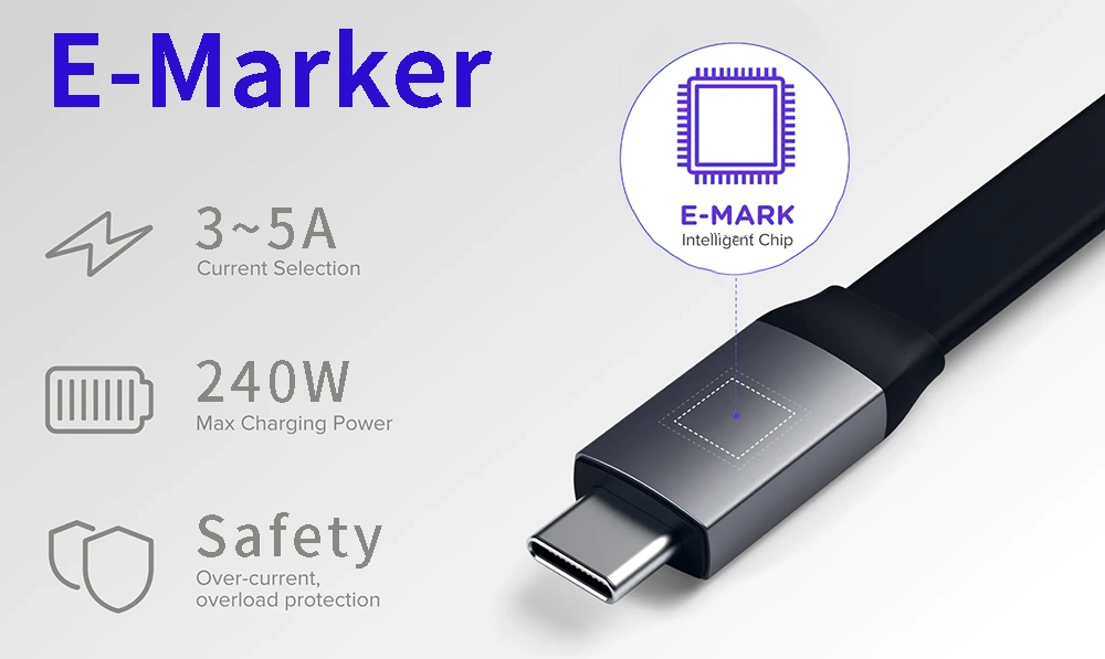
Have you ever been surprised when using the latest USB PD cables, how intelligently they grasp and manage the power to my electronic devices? This is where the magical “E-Marker chips” in electronic devices come into play.
Today, let us explore this high-tech technology hidden in USB cables and learn how it ensures that charging, transmitting and using power become more intelligent and efficient.
What is e-marker chip?
E-Marker, or Electronic Marker, is a smart chip used in the latest USB connector iteration, USB Type-C, to communicate between the power source and the power-sink device. The chip is cleverly embedded into the latest USB-C cables and acts as a communication intermediary between the power source (like a charger) and the device you’re connecting or charging. It plays a vital role in ensuring the secure exchange of data and power between the two ends.
Think of the E-Marker as the cable’s intelligent assistant, providing a wealth of information about the cable itself. This includes details such as its length, power-handling capabilities, supported USB signal types, video support, and even a unique product ID. This chip is a necessity for USB Type-C cables capable of handling 5 amps or more, typically signifying their ability to manage over 60 watts of power.
If you’re dealing with a USB Type-C cable that needs to transfer data faster than 480 megabits per second (like the speedier USB 3.0 and above standards), it’s likely got an E-Marker chip inside. This chip is particularly crucial for USB 3.1 and higher versions because the USB-IF community insists on including the E-Marker in these Type-C cables.
Due to the substantial variation in functionality among Type-C devices, considering the cable in your decision-making process is crucial. For instance, if both the source and receiving devices require 100W of power, but the cable can handle a maximum of only 10W, issues may arise. Conversely, if the power source and receiver provide the full 100W of power, the cable could fail and potentially pose a safety hazard. Therefore, negotiations for power transmission, including the power source, receiver, and cable, must occur before enumeration.
Thanks to the microchip, the E-Marker chip, located on the cable connector head, this communication becomes possible. The cable can convey its capabilities to the source and receiving devices, allowing them to make the necessary adjustments. The E-Marker chip acts as an intermediary in the negotiation process, often having the final say in how the source and receiving devices communicate effectively.
Characteristics of E Marker chip.
The E-Marker provides the cable characteristics including the cable length, the maximum supported current and voltage, the type of USB signal, the vendor and product ID, any alternate mode support, and much more. Knowing about the E Marker chip may be important for people buying custom USB C cables, but how do you know if your USB cable requires it? The following are some characteristics of USB cables and E-Marker chips, hoping to help you understand better:
- Influence on current transmission: The E-Marker chip mainly affects the current transmission of the USB cable, but does not affect data transmission. This is because in USB cables, power supply and data transfer speed are two independent factors. For example, for an A to C or C to C USB 2.0 cable, its theoretical data transfer speed is only 480Mbps. However, it can support current transfer capabilities up to 3A or even 5A.
- Data transfer rate exceeds 5Gbps: For USB cables that support data transfer rates above 5Gbps (USB 3.0), a corresponding chip needs to be used in the TYPE C connector to process data. These chips are responsible for handling high-speed data transmission, not the E-Marker chip.
- Current requirement exceeds 3A: High-quality 16-core or 24-core USB C cables on the market can usually support 3A current transmission, provided that the red and black power supply wires are larger than 20AWG. However, when the charging demand of the device exceeds 3A, an E-Marker chip is required for current detection. Of course, even for 3A cables, an E-Marker chip can be added to improve the stability of current transmission.
In short, the E Marker chip mainly affects the current transmission capability of the USB cable and does not involve data transmission. If your device requires high current transfer or a current requirement in excess of 3A, then considering a USB cable with an E-Marker chip may be a wise choice. However, for general purposes such as data transmission, the E-Marker chip is usually not necessary.
How does the E Marker chip handle power delivery?
Basically, an E-marker ensures a cable only transfers power at the rate that the device can handle and that it is able to transfer higher powers without any safety concerns such as overheating. When a USB-C cable with an E Marker chip is connected between a power source and a receiving device, they engage in an intelligent exchange of data to determine how to handle power transfer. Now, let’s take a closer look at what power packets are made of and how they are transmitted.
Data packet structure for power transmission:
- Preamble: This part allows the receiving device to lock onto the communication signal by sending a series of 1s and 0s, ensuring that the receiving device can synchronize with the transmitted clock in order to correctly parse the data.
- SOP (Start Frame/Start Flag): SOP defines the type of communication and indicates whether the packet is transmitted between ports or between the cable and the power supply. SOP is used to identify the direction and participants of power transmission. For communication between devices we use SOP packets, and for communication between cables and power supplies we use SOP*.
- Header sequence: The header sequence contains some key information, including the initiator of the request (whether it is an upstream device or a downstream device), the ID number of the transmission, and how many data packets are to be sent subsequently.
- Data package: The data package contains some information about the supplier ID, product ID and specific functions. This information is part of the E-Marker chip and helps determine how to handle power delivery.
- CRC (Cyclic Redundancy Check): After the E-Marker information is read, a CRC data packet is sent to ensure that the sent data packet is not damaged and can be received correctly. CRC checks ensure the integrity of data packets transmitted over the bus. At the end of the data packet, there will be an “end of data packet” flag to confirm that the PD data packet being sent has been transmitted.
Communication process of power transmission:
The PD negotiation process must first resolve the cable issue, which is called SOP prime. For any power contract over 3 amps or 60 watts, SOP negotiation is required. Fully functional USB C fast-charging data cables are required to have an E mark indicating power-carrying capabilities. Once cable capabilities are determined, the USB PD negotiation process can continue. To ensure safe and efficient power transmission. Below is the power transmission process simplified into eight stages:
- Cable identification:When PD negotiation begins, the device will first confirm the capabilities and characteristics of the cable to ensure that it can support the required power transmission.
- Receiver confirmation:The receiving device (such as a mobile phone or laptop) sends a confirmation message to the sending device (such as a charger or power adapter) indicating that it is ready to receive power.
- Request power: The receiving device will send a request to the sending device, requesting a specific power level or charging speed, based on the device’s needs and supported specifications.
- Confirm request: The sending device will confirm receipt of the request and check whether it can provide the required power level.
- Accept request:If the sending device can satisfy the request, it will accept the request and be ready to provide the required power.
- Confirm Acceptance: The sending device will send a confirmation to the receiving device indicating that it is ready to provide power.
- Ready:The sending device is ready to provide power and sends a ready signal to the receiving device.
- Negotiate power level: Finally, both devices will negotiate the exact details of power transmission, including current, voltage, and power level, to ensure safe and efficient charging.
It is important to note that if a malfunction or device incompatibility occurs during the negotiation process, power transmission may fail to ensure the safety and reliability of connected devices. This process is the key to achieving safe, efficient, and reliable power transmission to ensure that the device can safely implement PD and QC fast charging.
Why does USB C cable need an E Marker chip?
With the rapid popularity of USB PD fast charging in mobile devices such as notebooks and mobile phones, we have found that many USB PD cables that support high current output are equipped with E-Marker chips. This tiny chip plays a vital role in modern mobile devices and chargers, but why is it so important?
Many USB PD chargers that support high power output are equipped with E-Marker chip USB-C cables. But the problem is, there are differences between different E-Marker cable types. Some can deliver up to 240W of power, while others can only deliver 60W. Some cables can achieve transfer speeds of up to 10Gbps, while others only support USB 2.0, with a maximum data transfer speed of only 480Mbps. Embed E-Marker in the USB-C cable to ensure that charging is under a safety protection mechanism when the power adapter output current is greater than 3A.
Does a USB C to C cable need an E Marker chip to support USB 3.2 Gen 2 speeds?
There is no direct connection between the USB 2.0/3.x/4.0 transmission standard and the E-Marker chip. The key lies in the power of the cable and the fast charging protocol. The E-Marker chip is only required when the power of the cable exceeds 20 watts and the current reaches 3 amps to ensure correct power communication between the device and the charger.
The latest USB 3.2 Gen1/2 and USB 4.0, Thunderbolt 3/4 and PD 3.0/3.1 protocols require E-Marker chips because they usually support data transmission up to 5Gbps and above and efficient power above PD 3.0/QC 3.0 Transmission capabilities. These versions and protocols are also backwards compatible, so high-quality USB Type-C cables need to carry an E-Marker chip to correctly identify the maximum degree of power adaptation supported between the host and device to support efficient data transfer and charging .
It should be noted that although USB Type-C cables have two ports, usually USB cable manufacturers only embed an E-Marker chip on one of the ports. However, we recommend that both interfaces on custom-produced USB cables be equipped with E-Marker chips, especially on cables with power exceeding 100 watts. The advantage of this is that the charger can read the chip information more reliably and ensure the stability of high-power transmission, especially when the cable length exceeds 2 meters, the performance is better.
When you use electronic devices, the E-Marker chip is only one of the factors that determines the efficient charging performance of the USB C cable. In order to support more stable charging speeds and video output capabilities, cables with better internal materials need to be matched. APPHONE has excellent raw material control and production control capabilities, and can provide stable and reliable production solutions according to customer requirements.
As a professional customized USB cable manufacturer, we are well versed in the secrets of E-Marker chips and lead the industry with customized production capabilities. We can provide you with high-quality, customized USB cable solutions with E-Marker chips.
Don’t worry about mismatched chargers or inefficient charging anymore. Work with us to make your product charging experience smarter and more convenient. Contact us now to initiate an inquiry and work together to create an excellent E-Marker USB cable!
How do I know if my cable has an E mark?
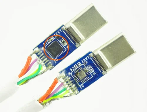
In fact, the E-marker cannot be recognized from outside the USB Type-C cable. The simple and crude method is to cut the plastic of the USB C cable connector port and see if there is a chip or just a blank pad on the connector PCB. If we want to test whether the cables we have are embedded with E-markers without loss, we must use professional instruments to test.
What does electronic marking mean?
E-Mark, short for Electronically Marked, is actually a protocol controller, and the idea is that a USB-C cable can be electronically marked with its power rating and data transfer rate. Secure transmission via maximum communication protocols identifying power sources and devices.
Do all USB C cables have chips?
All USB-C cables must be able to carry at least 3 A, but some cables that can carry 5 A may support 100W or more. USB-C to USB-C cables that support 5 A current must contain a programmed electronic marking chip (also called an E-Mark chip) to identify the cable and its current capabilities.
Share This Artcle:

Fast delivery
Fastest delivery within 22 days

Quick proofing
Fastest 3-day proofing cycle

After-sale protection
24-month long warranty

1V1Customer Service
Professional customer service follow-up


